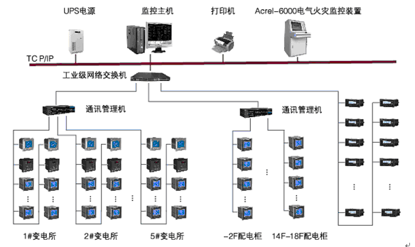
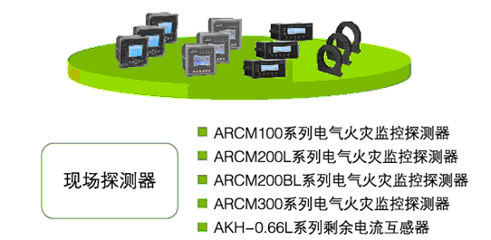
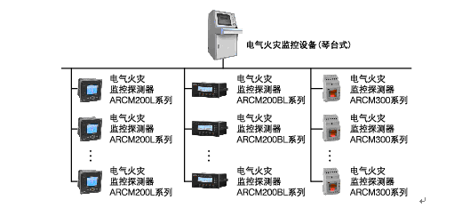
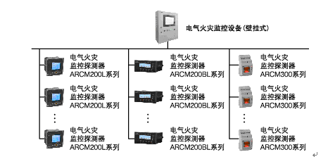
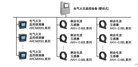
Xu Shuang Ankerui Electric Co., Ltd., Jiading, Shanghai 201801 0 Preface In recent years, the proportion of electrical fires in China in the total number of fire accidents has increased. The fire caused by electrical faults has been listed as the leading cause of fire in urban fire accidents. Comprehensive monitoring and prevention of electrical fires has become an indispensable and important part of engineering construction and design. 1 The main causes of electrical fire 1) Phase-to-phase short circuit due to installation and wiring negligence 2) humid environment 3) Leakage current 4) The rated current of the circuit breaker (fuse) is too large 5) The cable current density is too large 6) The actual ampacity of the line exceeds the design ampacity 7) Three-phase load imbalance 2 The main means to prevent electrical fires Promote the use of electrical fire monitoring system devices, and actively transform the electrical lines of old buildings to eliminate potential fire hazards. The circuit design fully considers the impact of growth factors and laying conditions on the ampacity, selecting a sufficient neutral section, and the terminal distribution line Total equipotential grounding and local equipotential grounding ensure construction quality and strengthen quality supervision and acceptance. 3 System Design Application Basis 1) GB50045-95 (2005 edition) "High-rise Civil Building Design Fire Prevention Code", which provisions in Article 9.5.1: high-rise buildings in the fire risk, personnel intensive and other places should be set leakage fire alarm system. 2) GB50016-2006 “Specifications for Fire Protection in Building Designâ€, in Clause 11.2.7, stipulates: The following places should be provided with residual current action electrical fire monitoring system. These places include various types: theaters, halls, warehouses, residential quarters, hospitals, shops, schools, and so on. 3) The relevant provisions of the national standard “Building electrical fire prevention requirements and detection methods†also explicitly require that “the residual current operation protector that automatically cuts off the power supply or alarm should be installed at the power supply inlet endâ€. 4) The products of the electrical fire monitoring system shall meet: GB14287.1-2005 "Electrical fire monitoring equipment", GB14287.2-2005 "residual current electrical fire monitoring detector", GB14287.3-2005 "temperature-type electrical fire Monitoring Detector" 5) Installation and operation of electrical fire monitoring system shall meet GB13955-2005 "Installation and Operation of Residual Current Operation Protection Device" 6) The power supply for the electrical fire monitoring system should meet the requirements of GB50052 "Design Specification for Power Supply and Distribution System" 7) The design of electrical fire monitoring system should meet the requirements of "Design Method for Electrical Fire Monitoring System" 4 The basic composition and working principle of the system 1) Basic composition Acrel-6000 electrical fire monitoring system adopts layered distribution and open structure design and consists of station management layer, network communication layer and field device layer. All electrical fire monitoring probes are connected to the communication server through a shielded twisted pair RS485 interface, using a MODBUS communication protocol bus type connection, and then enter the industrial switch through the Category 5 TCP/TP protocol, and then reach the monitoring host through the optical cable. a) The field device layer is mainly connected to various types of instruments and protection devices used for the collection and measurement of electrical parameters in the network, and it is also a necessary basic element for constructing the monitoring system. The monitoring equipment can receive the alarm signal from the electrical fire monitoring detector, issue the sound and light alarm signal and control signal, indicate the alarm location, and record and save the alarm information. It is the management center of the system. It not only shoulders the burden of collecting data, but it is also a terminal component that executes background control commands. The monitoring equipment has the functions of automatic switching between main and standby power to ensure the stability of the system. b) The communication control layer is mainly composed of communication server, interface conversion device and bus network. This layer is the bridge for data information exchange. Different interface conversion devices provide various interfaces such as RS485 and Ethernet, flexible networking methods, and support for peer-to-peer communication, fieldbus networks, Ethernet, and other types of configuration networks. The communication server is mainly used to directly transmit various control commands of the host computer to the field instrument and instrument, and is responsible for collecting, classifying, and storing the data information sent back by the field instrument, such as voltage/current and other electrical parameters and input switch status. , modify the internal parameters of the instrument or various control relays open/close operation commands; c) Management The monitoring and control layer is for the management personnel of the monitoring network, and this layer directly faces the users. This layer is also the uppermost part of the system, mainly by the electrical fire monitoring system software and necessary hardware equipment such as computers, printers, UPS and so on. The software part has a good human-computer interaction interface. It reads the various data information collected by the front-end machine through the data transmission protocol, and is automatically calculated and processed to reflect the operating status of the site by means of graphics, digital display, and sound. Accept the operation command of the management personnel, send and check the execution status of the operation in real time to ensure the normal operation of the power supply unit. The basic principle is that when the current, temperature and other parameters in the electrical equipment are abnormal or abrupt, the terminal probe (such as the residual current transformer, temperature sensor, etc.) uses the electromagnetic field induction principle and the temperature effect to collect the information. And sent to the monitoring probe, after amplification, A / D conversion, CPU analysis and judgment of the change in amplitude, and compared with the alarm set value, once the set value is exceeded, then send an alarm signal, but also to the The monitoring equipment is further identified and determined by the monitoring equipment. When it is confirmed that a fire may occur, the monitoring host issues a fire alarm signal, turns on the alarm indicator, sounds the alarm, and displays the fire alarm and other information on the LCD. The on-duty personnel quickly checks and handles the accident scene according to the above information, and sends the alarm information to the centralized console. 5 System Design and Application 1) Typical networking scheme a) Large-scale construction group network plan Large buildings, high floors, multiple buildings scattered. Acrel-6000/Q electrical fire monitoring equipment +Acrel6000/B electrical fire monitoring equipment + electrical fire monitoring detector three-tier structure networking mode, to facilitate regional management, using RS-485 network communication, Ethernet communication, to meet the communication High real-time requirements. b) Large-scale single-unit construction network plan Large-scale single building adopts Acrel-6000/Q electrical fire monitoring equipment + electrical fire monitoring detector two-tier structure networking mode, comprehensive monitoring and management functions, high cost performance, using RS-485 network, communication media using shielded twisted pair, Meet the high real-time communication requirements. c) Medium-sized construction network plan The medium-sized single building adopts Acrel-6000/B electrical fire monitoring equipment + electrical fire monitoring detector two-tier structure networking mode, cost-effective, cost-effective, using RS-485 network, to meet the high real-time communication requirements. d) Small building electrical fire monitoring system Small buildings, using Acrel-6000/B electrical fire monitoring equipment for monitoring, cost-effective, cost-effective. Ankerui Electric Co., Ltd. undertook the residual current electrical fire monitoring system for the Anting Station on Line 11 of the Metro Line 11 in August 2011. The project is divided into five districts: A1, A2a, A2b, A3, A4 and A5. 196 ARCM200-J1 residual current electrical fire detectors were installed. The detector is composed of an RS485 bus and a fire monitoring system that is located in the monitoring center's duty room electrical fire monitoring equipment. Acrel-6000 electrical fire monitoring equipment is adopted. It has functions such as centralized dispatch, control, protection, monitoring, and display, and integrates electricity safety management. The advantages of analysis and recording in one intelligent can greatly reduce the incidence of electrical fire in the application. The system mainly realizes telemetering, remote adjustment, remote control, and remote communication for 196 detectors scattered in the building, facilitating monitoring and management; monitoring leakage current, over-current signals, and emitting sound and light alarm signals to report fault locations. Monitor fault point changes and store various fault signals; display and alarm according to the type of signal provided by the detector, including alarms such as split/close, residual current fault, over-current fault, voltage fault or temperature; The function checks the short circuit and open circuit of the communication line. references: [1] Ankerui Electric Co., Ltd. System Solution, 2013.1. [2] The principle and application guide of power electric measuring digital instrument Ren Chengcheng, Zhou Zhong, China Electric Power Press 2007.4. About the Author: Xu Shuang, female, undergraduate, Ankerui Electric Co., Ltd., the main research direction for electrical fire monitoring, Email: mobile phone "Atlas of Design and Application of Electrical Fire Monitoring System" (atlas number: ACR12CDX401) edited by Ancorui Electric Co., Ltd. and Shandong Electric Power Technology Information Network, this atlas combines with Acrel-6000 electric fire monitoring system The characteristics of the product, based on electrical design specifications, meet the requirements of electrical fire prevention and early warning of buildings to achieve the purpose of curbing electrical fires. The Atlas is applicable to the design and application of electrical fire monitoring systems for 220V/380V power supply and distribution systems in civil buildings and general industrial buildings newly built, expanded and rebuilt, and includes the selection and installation of system equipment with special requirements. The building needs to be selected in combination with the actual conditions of the project. If you need an atlas, please provide your organization's name, department, address, zip code, contact person, contact telephone number, email address, fax, email@qq.com or QQ to Ankeru Xu cream engineer, Ankerui Electric Give away. Two Wheel Electric Balance Scooter has operated by self balance with inside high technique Solid-state Gyroscopes,two blushless motor wheel and precision controller.It has two kinds, with handle and without handle.Motor wheel has 6.5inch, 7inch,8inch and 10inch.For motor power there are 500w and 700w. Two Wheel Electric Balance Scooter Two Wheel Electric Balance Scooter,Self Balance Board,Wheel Self Balancing Electric Scooter,Electric Scooter Two Wheels Yongkang Longyin Industry and Trade Co., Ltd. , http://www.cnlongyin.com