1 System Overview Currently, portable temperature, air pressure, and humidity data acquisition systems used in industry, agriculture, fishery, and meteorology are basically wired, and their portable performance is mainly reflected in the ease of movement and erection, etc. In the actual use process, system wiring and connection establishment are still required, and the volume is relatively large and it is inconvenient to carry and cannot meet the requirements of portable devices. Related Products: Agricultural Environment Detector Portable Agricultural Environment Monitor Artificial Climate Box Isolation Gown,Non-woven Isolation Gown,PE Coated Isolation Gown,Nonwoven Lamination Gown XINLE HUABAO MEDICAL PRODUCTS CO.,LTD. , https://www.golbaltravel.com
The portable small-scale meteorological station system mainly includes the acquisition and transmission, reception and data processing. The collection and transmission parts complete the automatic data collection, data wireless transmission, and the related settings for receiving instructions. The erection method can be determined according to the specific needs. The receiving and data processing part completes the data reception and display, and receives the keyboard instructions to make related settings for the two parts, triggering an alarm according to the set alarm mode. Due to the small number of components in the system, it can be made into a handheld or desktop. Hand-held data display mode should adopt liquid crystal display mode, on the one hand to save energy, on the other hand can greatly reduce the appearance of the volume, more suitable for portable. Desktop receiving and data processing can be digital tube display, the effect is better when viewed from a distance.
2 system work composition The portable small weather station system hardware mainly by the monolithic integrated circuit and the memory unit, the AD conversion unit, the sensor unit, the wireless transmission unit, the power source unit composes, like chart 1 shows.
2.1 Microcontrollers and Memory Units Microcontrollers for small portable weather stations use Atmel's AT89S51. S1, C3, and R1 constitute the reset circuit of the microcontroller, and the C1, C2, and 11.0592 MHz crystals form a stable clock circuit, which guarantees the reliable operation of the microcontroller. S51 pin 31 (/EA/VP) is tied high to use the internal program memory. 24C01 Used to save the relevant parameter setting data.
2.2 A/D Conversion Unit The AD conversion uses the common 8-bit dual AD converter ADC0832. The operating clock is provided by the D flip-flop 74LS175 divided by 8 on the clock signal (about 1.8434MHz) output from the ALE pin of the microcontroller. The connection between the microcontroller and the sensor is shown in Figure 1. 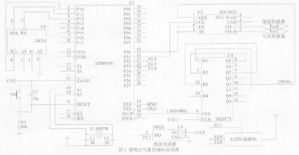
2.3 Sensor Unit The sensor mainly includes 3 kinds of sensors such as temperature, humidity and air pressure. The temperature sensor adopts DS18B20, a “first-line bus†digital temperature sensor from Dallas Semiconductor, with a temperature measurement range of -55 to +125°C and an accuracy of ±0.5°C in the range of -10 to +85°C. The on-site temperature is directly transmitted to the SCM by the “one-line bus†digital method, which greatly improves the anti-interference performance of the portable small weather station system and is suitable for on-site temperature measurement in harsh environments. The humidity data is collected using the GY-HRM201 moisture-sensitive resistor module as a sensor. Easy to use, an external 5VDC power supply can output a changing voltage signal. Pressure sensor uses Freescale (Motorola) MPXM2202 pressure sensor, measuring range is 0 ~ 200kPa, power supply is 10VDC, maximum 16V. In order to reduce the power consumption of the entire acquisition system, the system uses an intermittent power supply mode for the humidity and pressure sensors and their peripheral circuits. That is, power is supplied before data sampling, ADC sampling is started after a delay of 50 ms, and the power is turned off after the conversion is completed. . The microcontroller program performs power management control through its I/O port P2.4. 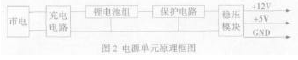
2.4 Power Supply Unit The instrument is powered by a high-energy lithium battery. The principle of the power supply unit is shown in Figure 2. The charging circuit consists of a switching power supply and a charge monitoring circuit, which automatically stops when the battery is full. The battery pack consists of four lithium-ion batteries, each rated at 3.7V, full of no-load voltage of 4.2V, and a total of 44.8V after four series connections. After the voltage output of the battery pack is discharged through the protection circuit, it is regulated by 12V and 5V regulator modules to output +12V and +5V to provide power for the entire acquisition system.
3 RF transmission This small weather station system uses a single RF transceiver chip nRF403 and PT2262/2272 codec chip to form a two-way data transmission channel, transceiver status conversion real-time control by the microcontroller. The transmission modulation adopts the transparent transmission method, the coded signal can be directly connected to the data input end of the transmitting module, and the demodulated signal can be output at the data output end of the receiver. 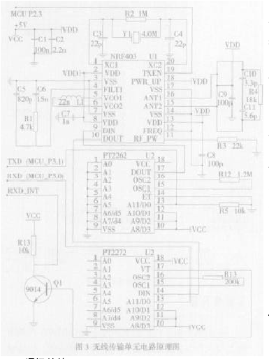
3.1 Circuit Schematic The schematic of the portable small weather station is shown in Figure 3. When idle, the microcontroller P2.3 outputs a low level and the nRF403 operates in the receive standby state. If there is a wireless transmission signal, the chip nRF403 enters the receiving state, and the received data is output from the DOUT port to the decoding chip PT2272. When the PT2272 decodes correctly, its VT terminal generates a positive pulse, which is sent to the external interrupt INT0 of the microcontroller after the 9014 phase-reversal, and generates a receive interrupt signal. The MCU enters the receive service program to complete data reception through the P3.0 interface (RXD). . When the timing data is transmitted, the microcontroller P2.3 output high level, immediately transfer the chip nRF403 from the receiving standby state to the transmitting state, and output the data to be transmitted from the P3.1 port to the data input port of the encoding chip PT2262, completing Coded directly to the DIN port of the chip nRF403 to complete the wireless data transmission. After the data transmission is completed, the P2.3 port of the 89S51 outputs a low level, and the control chip nRF403 enters the reception waiting state again.
3.2 Communication Protocol The transmission and reception of small weather station system data are two different channels. The data transfer rate is fixed at 1200 baud, so the serial port settings for both the sending and receiving microcontrollers are the same. The transmission of data is divided into two cases. One is the collected data, 2 bytes each of temperature, pressure, and humidity, followed by the corresponding 6-byte inverted code, used as an error control; the other is a control command. , complete the corresponding control of the receiving end. There are two types of communication protocols to send, one is an instruction packet and the other is a data packet, as shown in Table 1. 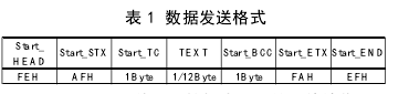
Start_HEAD: Transmission start flag, the purpose is to synchronize the receiver and transmitter.
Start_STX: Data transfer start flag.
Start_TC: Distinguishes the code, distinguishes whether it is the instruction packet or the data packet that conveys.
TEXT: The body part, when transmitting the instruction packet, has only one byte and the value is 00H, and when transmitting the data packet, it is 12 bytes of temperature and humidity data (positive and negative code).
Start_BCC: error detection, sum check code (odd odd/even), accumulates and checks Start_TC and TEXT together.
Start_ETX: End of data transmission.
Start_END: ​​Transmission termination flag indicates that the sender will immediately stop sending.
The Start_TC field controls the meaning: The upper 4 bits are the signature and the lower 4 bits are the specific parameters of the control command. When sending a packet, the signature is 1111B and the lower 4 bits are 0000H. The specific meaning when sending an instruction packet is as follows:
1100B: Data error, request to resend once.
1101B: Set the acquisition interval.
1011B: Reset the MCU.
1010B: Initialize all acquisition modules.
Other: spare.
4 Conclusion This article designed a portable small weather station to make temperature, air pressure, humidity measurement and data transmission more convenient, hardware connection is simpler, the use of a custom data transmission protocol method is relatively simple, double-level error control can be to a large extent Improve the accuracy of data transmission.