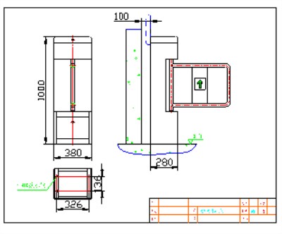
Welcome to use our company's channel gate system, I hope this manual will bring you convenience when installing the machine. Swing gates and wing gates are intelligent channel management equipment developed and produced by our company for many years. The equipment integrates machinery, electronics, microprocessor control and various reading and writing technologies into one. The intelligent control and management of the channel is realized by configuring various reading and writing devices, control boards and software. The shape of the equipment is stamped and formed with stainless steel plate, which is beautiful and elegant, rust-proof and durable, and adopts a standard electrical interface to the outside, which can easily integrate card readers such as barcode readers, ID cards, IC cards, fingerprint readers, facial recognition devices, etc. On the equipment; provide a civilized and orderly way for people to enter and exit, and at the same time prevent illegal people from entering and exiting; in addition, the system is specially designed to meet the requirements of fire protection, in the event of an emergency, to ensure that the passage is unobstructed, and facilitate the evacuation of personnel . 1.2. Features 1) With zero self-check function, it is convenient for users to maintain and use; 2) Illegal entry has an alarm prompt function; 3) Through the small buttons on the main control board, the running state of the programmable device can be programmed; 4) Anti-collision function, when no opening signal is received, the shutter (swing arm) automatically locks; 5) Infrared / mechanical double anti-pinch function, when resistance is encountered during the reset process of the shutter (swing arm), the motor automatically stops working within a specified time, and the force is very small, and an alarm signal is issued at the same time; 6) With automatic reset function, after the pedestrian reads the valid card, if the system does not pass within the specified time, the system will automatically cancel the pedestrian's access authority; 7) Synchronization function of ram (swing arm); 8) The power-off channel is automatically opened normally, and the power is automatically closed; 9) Sound and light alarm function: including illegal intrusion and trailing alarm; 10) The unified standard external electrical interface can be connected with a variety of card readers, and can be remotely controlled and managed by the management computer; 11) One-way or two-way control of personnel entry and exit; 12) The whole system runs smoothly with low noise; Scalable functions 1) Counting function 2) Lengthened chassis, color selection of swing gate material or gate material 1.3 Main technical parameters 2 Product dimensions 2.1 Equipment dimensions Equipment outline dimensions Product structure and working principle 3.1 Channel gate mechanical system The channel gate mechanical system is divided into two parts: the chassis and the movement. The chassis is used as a carrier, on which the electric control box, direction indicator, air circuit breaker, transformer, reading and writing device, infrared radiation, etc. are installed. Frame, drive shaft, gate / swing arm, limit switch, etc .; The electric control system is composed of main control board, battery, infrared radiation, direction indicator, alarm, limit switch, transformer and so on. 3.3 Working principle of the system 4. Equipment installation and commissioning 4.1 Equipment installation 1. The depth of the buried PVC pipe should be greater than 60mm, the height of the exposed ground should be greater than 50mm, and the outlet should be bent back to prevent the pipe from entering the water 2. When installing channel gates, the left and right gates of each channel should be aligned; 3. Connect the system protective ground wire; 4. If the equipment is used outdoors, a cement platform with a height of 100 ~ 200mm should be built at the installation place to isolate the moisture, and sunscreen and rainproof facilities such as ceilings should be added; 5. After the equipment is installed, the status check and function debugging are qualified before it can be put into normal use. 4. 2 equipment function debugging and access control installation After the equipment installation is completed, use the manual switch test. After the test is normal, the following function debugging can be carried out! Swing gate / wing gate debugging instructions 1 Preparation before commissioning Check the wiring according to the wiring diagram, check that the power wiring and other wiring of the entire device are correct, and can be debugged after power-on! Each machine is equipped with a wiring diagram on the cover of the electric control box, and it is operated against the wiring diagram during installation. The protection of the equipment must be reliably grounded, otherwise it is not allowed to be used. 2 access controller installation If you want to install the access controller and card reader on the purchased equipment, first ensure that the output signal of the access controller is the switch signal (dry contact signal), and if it is the voltage signal, please add a relay. Please use external power supply for the access controller. Do not take power from the device at will. One channel needs to be equipped with a dual-door control board for card access. The access control output terminal is connected to the 2-channel COM, NO, and the signal input terminal of the main board of the swing gate or wing gate is the three ports of the manual switch configured by the company. Box 8P-1 position, the common terminal is VDD, and the opening signal is left or right. If the opening direction of the swiping card is inconsistent with the passing direction, exchange the two NO terminals of the access control, or the signal lines of the left and right openings of the wing gate control board connected from the access control board. 5. Equipment operation instructions 5.1 Before the equipment is put into use, it must pass the button test, and it can be put into use only after the normal commissioning; 5.2 When the equipment is powered on, it is strictly forbidden to stand in the channel; 5.3 When a pedestrian reads a cartoon, the direction indicator sign does not turn green, and it is strictly forbidden to enter the passage; 5.4 When pedestrians pass through the passage, do not stay in the middle of the passage for a long time; 5.5 When passing through the gate, don't be crowded, keep a certain distance between people; 5.6 It is strictly forbidden not to read the card, and quickly pass through the gate; 5.7 It is recommended to mark the instructions for the passage of the machine in a conspicuous place in the work of the equipment, and guide the passers-by to pass the gate passage in a safe and orderly manner; 5.8 The equipment should be properly managed when it is not working, and it is strictly prohibited to knock or shake the equipment; ! caveat: 1. Please do not use this machine when there is lightning in outdoor use to prevent damage to this machine ; 2. When restarting after rain stoppage, please open the door and lid of the chassis to ventilate, and then turn on the power after the water vapor inside the chassis is dry, otherwise it will damage the circuit board; Appendix 1 Commissioning Instructions for System Parameters 1. General description 1. The display refers to the 3-digit LEDs displayed from left to right on the main control board, and the default display is RUN; 2. From left to right, the three keys are INC key, SET key, DEC key, SET key for entering and exiting Menu function setting; INC key is used to add 1 to the parameter to be set; DEC key is used to decrement the parameter to be set by 1; 2. Settings for entering and exiting the menu 1. Enter the menu: Press the SET button, and release the SET button when you hear a beep, then the display shows "P00", indicating that you have entered the menu setting state, and you can use the INC button and DEC button To select the function number of the setting function; press the INC key, the function number increases by 1, and the DEC key function number decreases by 1; there are 18 kinds of function settings, you need to use: P00: Exit the menu setting function. When P00 appears, press SET to exit the menu setting; P01: Infrared blocking setting, = 000 blocking anti-pin infrared blocking, = 001 blocking anti-pin infrared blocking; P02: The maximum running time of the gate, the unit is 0.1 second. If the time is set to 60, it is 6 seconds. If the gate is not closed in 6 seconds when the gate is closed, the gate will stop closing (the default value is 60) P03: Pedestrian passage time, in seconds. If the time is set to 10, it is 10 seconds. After the pedestrian swipes the card, the card will be canceled if it does not pass within the set time. (The system default is 10) P04: working mode (the system default value is 000) = 000: two-way swipe card = 001: Swipe in and out, free out, = 002: Free access, swipe out = 003: Freedom to enter, freedom to exit = 004: Forward opening (one-way) = 005: Outbound opening (unidirectional) P05: Advance door opening speed: the speed of the gate from closing to inward to forward opening to in position. (The system default is 10) P06: advancing closing speed: the speed of the gate from the advancing opening to the closing position. (The system default is 10) P07: Outward door opening speed: The speed of the gate from the closed position to the outbound opening position. (The system default is 10) P08: Exit-to-door closing speed: the speed of the gate from the opening-to-open to the closed-to-position. (The system default is 10) P09: Pedestrian passage time is considered to be one person within the set time (the system default is 10) P10: The forward counter is cleared. When P10 is displayed, press the SET key and then display C-L. After pressing the INC key, the system sends a forward count clear signal and the forward counter is cleared. P11: The outgoing counter is cleared. When P11 is displayed, the SET key is pressed and C-L is displayed. After pressing the INC key, the system sends a clear signal to the count and the outgoing counter is cleared. P12: With memory or without memory function setting, the default bidirectional without memory function = 000: two-way with memory, = 001: Inbound without memory, outbound with memory. = 002: Inbound with memory, outbound without memory. = 003: Two-way without memory. P13: Device communication address, which is the number of the machine. The range is 1-255. (The system default value is 001) P14: Device type = 000: The device is a swing gate = 001: The device is a wing gate P15: The system restores the default value. When the P15 is displayed, press the SET button. After the button is displayed, P-2 is displayed. Press INC at this time. The key system restores the default value. P16: Adjust the opening direction when the communication opens. = 0 to one direction, = 1 to the opposite direction. If the two gates of the same channel are opened in the same direction when swinging the gate, set one side to 0 and the other to 1. P17: Infrared delay function: how long does the pedestrian delay to close the gate after passing the system, there is no delay when the gate is normal, if the gate is longer, the pedestrian will immediately close the gate after passing and will hit the pedestrian to adjust the delay to avoid hitting . 2. Exit menu setting : Press INC key or DEC key. When P00 appears, press SET key to exit menu setting. (The smaller the above speed value, the faster the speed.) Mini Power Trowel,Multiquip Power Trowel,Double Pan Power Trowel,Small Electric Power Trowel Shandong Nuoman Engineering Machinery Co., Ltd , https://www.chinanuoman.com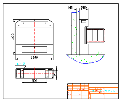
3. 2-channel gate electric control system
! Warning :
5.9 When the equipment is in the closed state, it is strictly prohibited to push or pull hard or hit the gate;