we are mainly in isuzu Water Cooled Engine , and we are good in quality and competitive in price. We can supply you variouse power engine . and they are often used for water pump and generator set . if you need any of them , please feel free to contact us for free .
We are able to providing professional power solution from 19KW to 134KW , Now we are recognized as a rapidly growing company that cares about the customes expectation constantly.
The engine is am internationally inspired supplier of wide ranges pf diesel engines in China , we have benn delivering great value ,through superior quality and reliable performance ., to meet diverse requirements in the field of diesel generator , marine , agricaultural equipments and construction applications etc.
Isuzu Diesel Engine, ISUZU Water Cooled Engine Shijiazhuang Houfeng Trading Co.,Ltd , http://www.hfdieselengine.com
SECCO (Shanghai Ethylene Cracker Complex Project) refers to Shanghai Ethylene Cracker Complex Project. It is jointly established by British BP, Sinopec and Shanghai Petrochemical. It consists of the following five sets of process equipment.
1.9 million tons/year ethylene plant (using ABB LUMMUS process technology), 200,000 tons/year aromatics extraction unit and 90,000 tons/year butadiene extraction unit.
A 2.5 million t/y styrene plant (using ABB LUMMUS process technology) and a 300,000 t/y polystyrene plant (using BP technology).
3.6 million tons/year polyethylene plant (using BP process technology) and 250,000 tons/year polypropylene plant (using BP technology).
4.26 million tons/year acrylonitrile plant (using BP process technology).
5Utilities and OSBL, including steam production, power generation, and tank farms.
The entire combined device is monitored and controlled by SECCO ICS (Integrated Con-trol System), which is composed of DCS, SIS, F&G, AHP, and GPC. DCS uses the FisherVousment DeltaV control system based on FF fieldbus; SIS is the instrument safety system; F&G (Fire & Gas) system is connected to the DCS system through redundant Modbus serial lines, and the DCS is used for fire alarm, smoke detection and other. The information related to F&G is displayed; Auxiliary hard-wired panel of AHP is equipped with emergency stop button, overload switch and signal and other components of SIS system; GPC (General Purpose PC) is used to complete CCTV and The implementation of LAN.
All devices consist of a Central Control Room (CCR) and fourteen outstations. The central control room is used to monitor and manage all process equipment and utilities. It is the most critical part of the combined devices. Each device will have several external stations. All field instrument signals are transmitted to the external station first, and then sent from the external station to the central control room. Controllers of DCS, SIS, and F&G systems are all placed in external stations. Each external station has an operator. Usually, no personnel are on duty. It is only used to facilitate the use of nearby operators, such as instrument debugging (including loopback). Test) etc.
Second, FF field bus characteristics
The Foundation Fieldbus is usually called the FF Fieldbus and is divided into two levels of H1 and H2 buses. H1 adopts the physical layer of field bus that accords with IEC 61158-2 standard; H2 adopts high-speed Ethernet as its physical layer.
The main electrical characteristics of H1 fieldbus physical layer are as follows: Bit synchronous digital transmission; transmission baud rate 31.25kbit/s; driving voltage 9~32V DC; signal current ±9mA; cable type shielded twisted pair; wiring topology Can be linear, tree, star or conformity; cable length less than or equal to 1900m (without repeater); branch cable length 30 ~ 120m; number of equipment hanging on the border is less than or equal to 32 (without repeater); Available repeaters are less than or equal to 4; applicable explosion protection methods are intrinsically safe explosion proof methods.
Third, FF field bus network composition
3.1 Network Topology
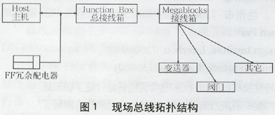
A Chickens Foot topology was used in the field, and each section had only one chicken paw, and the compound chicken-claw topology was not allowed in the SECCO project, as shown in Figure 1. 
3.2 Bus power supply
The H1 fieldbus completes power supply and two-way digital communications to multiple field instruments on a single shielded twisted pair cable. The H1 network card equipped with the control system is usually only responsible for two-way communication with field instruments. The bus power supply needs to be completed by a dedicated FF distributor.
The H1 bus is segmented. Each H1 network card has two ports. Each port is connected to one segment. Each segment needs to have a FF distribution device. Both ends of the bus also need a termination resistor to eliminate the echo of high-frequency signals.
The fieldbus network has many two-wire field devices that require external power supply. The general operating voltage is 9-32V, typically 24V. Each device draws current between 10 and 25mA. In order to ensure sufficient voltage to maintain operation, it is necessary to know the power consumption, location, cable impedance and power supply voltage of each device when configuring the field bus area, calculate the voltage drop on the main line and the branch line respectively, and finally obtain the field device. The voltage on.
3.3 Cables
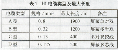
The physical signals, terminals, power supplies, and intrinsic safety of the field bus are different from those of conventional meters. The cables used by both must be distinguished. The cable types, specifications, and maximum lengths for the H1 fieldbus with a communication rate of 31.25 kb/s are listed in Table 1. Cables should be selected according to the needs of the project. Type A is generally preferred for new devices; Type B can be used as an alternative; Types C and D are used only for retrofitting devices. 
In the project, attention must be paid to the shielding and grounding of the cable, and the type A and B shielded cables are preferred. Cables of type C and D can also be passed through a metal tube for shielding. After using shielded cables, the shield of each branch must be connected to the mains, and then be grounded together; the polarity of the connection between the cable and the device must be observed. Therefore, the Manchester signal used by the fieldbus is an alternating voltage, changing one or two polarities per bit. Only this AC voltage exists in non-powered networks. In the power supply network, the alternating voltage is superimposed on the DC voltage supplied to the device. In either case, the fieldbus acceptance circuit only pays attention to the alternating voltage. The positive and negative voltage jumps mean different things. Therefore, the fieldbus signal is polar. Bus power supply equipment is also polar. Must be connected together with the same polarity. Use color-coded cables for easy construction. At present, there is also a network-powered non-polar device that can perform automatic polarity detection and correction, correctly accept signals of different polarities, and can be blindly connected when used.
3.4 Short circuit protection
Multiple devices are connected in each segment of the FF field bus. If any one of the lines in the FF field bus is short-circuited, it will cause fatal damage to the entire segment. Therefore, we must pay full attention to the short circuit of the FF bus. This is because: First, the FF bus is connected to a number of field instruments on a pair of shielded twisted pairs. Short-circuiting any one of the instruments will cause a short circuit in the entire bus. When the instrument housing is maintained online, it causes a short circuit. Even if such a short circuit is short-lived, it will endanger the normal operation of the entire segment of the bus. Secondly, due to a short circuit at any point on the bus, the entire segment is short-circuited, making it difficult to find and eliminate short-circuit faults. For example, there are 8 field instruments attached to a certain bus and a network terminal at the end. The installation position of these 8 instruments may be 30m or 3 levels apart. When the bus is short-circuited, the meter maintenance personnel cannot intuitively judge which table is short-circuited, nor can it be judged whether there is only one short-circuit point or more than one. Must be prepared to check all 8 instruments. It may take an hour and a few hundred meters back and forth to climb up and down several platforms to find the problem.
To solve the problem of short-circuit protection, the most direct and effective method is to use a field junction box with bus short-circuit protection. This kind of short-circuit protection terminal box can make the short circuit of any one instrument not affect the work of other instruments in this bus segment, and make the maintenance personnel of the instrument can see the short-circuit fault point at a glance in the control room.
3.5 SECCO Specific Rules
In the use of the FF fieldbus in the SECCO project, a number of regulations have been formulated according to the actual conditions, and they are briefly as follows:
1 Valves and transmitters in a standard control loop should be in the same segment. For example, in a pressure loop, the pressure transmitter and valve should be in the same segment.
2 At least one meter must have LAS backup function in each segment of the site.
3 The number of meters attached to each section does not exceed 12 units. Under normal circumstances, the design load of each segment is 9 and the other 3 are reserved for future use.
4 No more than 2 valves in the load of each section.
5 The number of instruments with a function block processing time of 0.25 seconds in one segment does not exceed three.
6 For standard control reverberation, the control (PID block) is set in the positioner. In cascade control, the main control loop is in the DCS and the secondary loop is implemented by the valve positioner.
7 For equipment that uses multi-point measurements, such as reactors that use multi-point temperature and multi-point pressure measurements, the meters should be evenly distributed across multiple segments.
8 The main LAS is located in the H1 controller and there is at least one backup LAS in the field device.
9 The length of the branch cable for a segment should not exceed 120 meters and each branch should be designed within 10 meters.
10 In the field, all FF fieldbus instruments are distinguished from traditional 4-20mA meters by using an additional orange trim at the end of the cable identification.
Fourth, the conclusion
The application of FF fieldbus technology in such a large-scale application in the SECCO project is rare in China. The fieldbus control system has reached the world advanced level in the field of industrial automation. From the installation, wiring, use of the instrument to on-site operation and maintenance, significant costs are saved. In future applications, it should give full play to its flexible topology, true interoperability and openness, and grasp the application technology of fieldbus control systems in engineering as soon as possible to maximize its function and better For production and management services.
Application of FF Field Bus in SECCO Project
I. SECCO Project