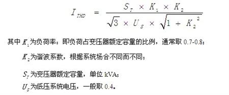
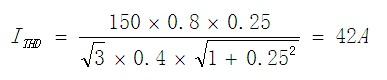
Xu Shuang Ankerui Electric Co., Ltd.    Jiading 201801 1 Introduction With the increasing application of power electronic converter devices, electrical energy has been more fully utilized. However, the wide application of non-linear power devices has produced a large number of distorted current harmonics. The flow of distorted currents in the power grid has caused harmonic voltages; harmonic pollution has increasingly threatened the safety, stability, and economic operation of power systems. This has a great impact on the linear load and other users of the same network. Harmonics have been accompanied by electromagnetic interference and power factor reduction and are classified as the three major hazards of the power system. Therefore, it is of great significance to understand the principle of harmonic generation and to study the elimination of high-order harmonics in power supply and distribution systems to improve the quality of power supply and ensure the safe and economical operation of power systems. Harmonic measurement is an important branch of harmonics and plays an important role in suppressing harmonics and solving harmonic generation problems. Therefore, the measurement and analysis of harmonics is an important task in power system analysis and control, and it is an important prerequisite for relay protection and fault measurement. ANAPF series active power filter devices are connected to the power grid in parallel and detect harmonics and reactive components of the load in real time. PWM inverter technology is used to generate one current harmonic component and reactive component from the converter. The reverse component is injected into the power system in real time, so that harmonic control and reactive power compensation are achieved. It has many functions such as improving power supply quality, increasing power factor and equipment utilization, saving energy and reducing loss, etc., thereby obtaining obvious economic benefits. The investment recovery period is generally 1 to 2 years. This article takes a chemical plant as an example to introduce the technical and economical performance of the low-voltage harmonic filter device. 2 user power profile A chemical plant in 2010 load distribution transformer capacity 5.2MVA, there are two 1.6MVA distribution transformers, one 2.0MVA distribution transformer, distribution transformer high voltage side voltage 10kV, low voltage side is 0.4kV, harmonic generation equipment Is a rectifier cabinet, rectifier equipment capacity of 1.344MVA. Focus on the (1.6MVA) 0.4kV side of the No. 1 transformer, as shown in diagram 1. The main harmonic current generated by the rectifier equipment has 5, 7, 11 and 13 currents. In fact, the measured values ​​are shown in Table 1. Figure 1 The load connected to the low voltage side of the distribution transformer No. 1 transformer was originally equipped with a 0.4kV reactive compensation capacitor near 600kvar. It has been damaged and replaced by about 60% after two years of operation. Due to lack of reactive power, the electricity tariff is adjusted to exceed 10 million yuan per year (2010 statistics ). In order to eliminate the adverse effects of harmonics, reduce production losses, extend equipment life, improve production efficiency and product quality, and also meet the requirements of reactive power compensation, a chemical plant replaces the original compensation capacitor bank with a low-voltage harmonic filter device. . Table 1 bus test value of No. 1 distribution transformer Harmonic times 5 7 11 13 Current (A) 483 312 176 184 3 ANAPF Active Power Filter 3.1 ANAPF Active Power Filter Device Specifications Wiring Three-phase three-wire or three-phase four-wire Access voltage 3×380V ±10% Access frequency 50Hz ±2% Dynamic compensation response time Dynamic response <4ms, full response time <20ms; On-off level 10kHz Function settings Only harmonics are compensated, only reactive power is compensated, both harmonics are compensated and reactive power is compensated; manual and automatic switching are performed. Harmonic compensation times 2-21 times Type of protection DC over-voltage IGBT over-current device temperature protection Overload protection Automatic current limit in the set value, no overload occurs cooling method Smart air cooling noise < 65db (in the cabinet and operating in the rated state) Working temperature -10°C to +45°C Working environment humidity <85%RH non-condensing Installation occasion Indoor installation Altitude ≤1000m (for use at higher altitudes) Incoming and outgoing ways Down in and out Protection level IP21 Intelligent communication interface RS485/MODBUS-RTU Remote monitoring Optional Overall size (mm) (W×D×H) 30A 50A 75A 100A 600×500×1500 600×500×1500 600×500×1800 800×600×2200 Weight (kg) Three-phase four-wire Three-phase three-wire 30A, 50A 75A, 100A 30A, 50A 75A, 100A 280 360 240 290 3.2 Reactive Power Compensation and Power Filtering Compared with general low-voltage capacitance compensation devices, the ANAPF active harmonic filter device not only has a reactive power compensation function, but also has a filtering ability, so that the user's harmonic current injected into the system is greatly reduced, Table 2 to 3 is a chemical plant in two Analysis of measured data under different conditions of electricity consumption. It can be seen from Table 2 that prior to the installation of the harmonic filter device, a parallel resonant circuit is formed between the original capacitor compensation branch and the load and the distribution transformer, so that the harmonic current of the capacitor and the distribution transformer is significantly amplified, and its resonance point is 13 times nearby. Table 3 shows that after inputting the harmonic filtering device, the user's power indicators have been significantly improved; no supply and demand reduction by 50%, power factor from 0.734 to 0.917, voltage and current distortion are reduced by half. After the ANAPF active filter device is put into use, it absorbs most of the higher-order harmonic currents generated by the rectifying equipment and greatly reduces the pollution to the power grid. After the No. 1 transformer is put into the harmonic filter device on the 0.4kV side, the harmonic current injected into the system is reduced from 301A to 108A 5 times, 7 times from 132A to 36A, 11 times from 48A to 24A, and 13 times from 36A. 12A; The absorption efficiency for the 5th, 7th, 11th, and 13th harmonics is 64%, 72%, 50%, and 66%, respectively. Table 2 Influence of original capacitance compensation equipment on each harmonic current (0.4kV side) Working conditions In/I1(%) 3 5 7 11 13 After the original compensation capacitor is put in 4.6 33.8 16.9 9.2 18.4 After the original compensation capacitor exits 4.6 26.1 10.7 3.0 1.5 Table 3 Harmonic filter devices improve power quality Working conditions Bus voltage (V) Bus Current (KA) Power Factor Three-phase apparent power (MVA) Three-phase active power (MW) Three-phase reactive power (Mvar) Total voltage distortion (THDy) Total current distortion (THD I ) Harmonic filter device before investment 389.4 2.3 0.734 1.57 1.15 1.067 5.3% 14.57% After the harmonic filter device is put into operation 397.3 1.834 0.917 1.26 1.15 0.53 2.55% 7.3% 3.3 Main Technical Features of ANAPF Active Power Filter Easy to use, easy to operate and maintain. DSP+FPGA all-digital control method, with extremely fast response time; advanced main circuit topology and control algorithm, higher precision, more stable operation; modular design, easy production and debugging; convenient parallel design, convenient expansion; perfect Bridge arm over-current protection function; 3.4 Harmonic Suppression and Capacity Design for Governance 3.4.1 Harmonic Current Estimation Harmonics are generated by non-linear devices, and the actual operating conditions of each device are different. Therefore, the actual harmonic current needs to be measured with special equipment. Considering the technical and economical performance of the equipment, the harmonic compensation current designed for the harmonic control device should be slightly larger than the system harmonic current. Because the measurement and calculation of the harmonic current itself are more complicated, and it is often difficult to collect enough harmonic data in use of the electrical equipment during design, the harmonic current can be estimated according to the following formula. 3.4.2 Harmonic Compensation Device Capacity Selection Compensation current selection principle: Harmonic current value obtained from the estimation. If passive harmonic suppression is adopted, the harmonic suppression current can be converted into a harmonic current per kilovar (kVar) converted into a current and then converted to a harmonic factor of 0.2-0.3 . For example, 100 kVar Harmonic Reactive Compensation Current is 144A. A factor of 0.2 reduces the harmonic current of 28.8A. If the active filter device is used, the design value can be selected based on the estimated value in the block diagram of the filter scheme. Example: The capacity of a company's distribution transformer is 150kVA , the transformer ratio is 10/0.4kV , the value of K1 is 0.8 , and the value of K2 is 25% . Try to use an active filter with a current rating to satisfy the harmonic suppression. Wave needs. According to the current harmonic formula is: Taking into account that there must be some margin, use 50A active power filter Therefore, the use of an active filter with a capacity of 35 kVA can satisfy the need for harmonic suppression. 3.5 List of ANAPF active power filter devices and major components Model Number: ANAPF50-400/B Reference price: 75,000 yuan/set The main product details: No. Name Model number Quantity 1 APF electrical cabinet 600X500X1800 1 2 Converter APFCOV-CVT50 1 3 Controller APFMC-C50 1 4 Reactor APF-RE.(S)DG-50 1 5 Active current transformer LT 1 08-S7 3 6 filter DL-1TH1 2 7 breaker NSE100N4063 1 8 Contactor LC1D65 M7C 1 9 MCB NDM1-63C32 1 10 Intermediate relay MY4NAC 2 11 R type transformer R320-0.38/0.22 1 12 Harmonic Detector ACR350EGH 1 13 wire 16mm 2 Some 14 wire 4mm 2 Some 4 Filter compensation device economic efficiency (1) Improvement of power factor: After the device is put into use, the power factor is increased to more than 0.9, and the power rate adjustment fee is converted into a bonus. That is, in the past, due to lack of sufficient power, the monthly payout rate adjustment fee was nearly 10,000 yuan. After the installation of the compensation filter device, The power factor is increased, and the monthly bonus rate adjustment fee is more than 500 yuan. (2) Compensate and reduce loss: After installation of filter compensation, effective local reactive power compensation can be performed. The No. 1 distribution transformer is equivalent to an increase of 310kVA. At the same time, the loss is greatly reduced. From March to November 2012, a certain chemical industry saving electricity costs 205,000 yuan plant, electricity consumption by the product 514 Kw .h / t, reduced 475.5 Kw .h / t, a decline of 7.5%. (3) Improve the product qualification rate: After the filter compensation device is put into operation, the harmonics are reduced, the voltage is stable, and the power quality is significantly improved. As a result, the product quality is improved, and the primary product rate is increased from 97.1% to 98.29&. Nearly 100t. (4) Prolonging the equipment life: After the filter compensation device is put into operation, the reduction of the load current, harmonic voltage and harmonic current will reduce the heat loss of the equipment, reduce the vibration, reduce the damage rate of the rectifier components, slow down the aging of the equipment insulation, and reduce the failure rate. This improves the level of safe operation. With the extension of equipment life, in the case of single capacitors, in the past, the plant was damaged by about 200 kvar capacitors, and the filter compensation device was put into operation for nearly 2 years. 5 Conclusion In summary, the harmonic filtering device takes into account the compensation and filtering functions. After the harmonic filtering device is put into operation, not only the 5th, 7th, 11th, and 13th harmonics are filtered out, but also the harmonic content is in line with the “Power Quality Common Harmonics of the power grid allow the requirements of harmonic current values. But also compensated for reactive power, so that the power factor reached 0.9 or more, to eliminate the phenomenon of fines for electricity charges. As the harmonics are filtered out, the pollution to the power supply system is reduced and the device is operating normally. Harmonic filter devices have extremely strong filtering capabilities and are fundamental measures to eliminate harmonic pollution and hazards. Therefore, they should be vigorously promoted and used. ã€references】 [1] Wang Zhaoan, Yang Jun, Liu Jinjun. Harmonic suppression and no power compensation [M]. Machinery Industry Press, 1998. [2] Yan Xiaoqing, Wang Zhaoan. Digital Model and Stability Analysis of Parallel Hybrid Active Power Filter [J]. Power Electronics, 1998, (4): 2 4~28. [3] Zhao Zhida. High voltage technology [M]. Beijing: China Electric Power Press, 2001. [4]Shi Chengjun. Study on Harmonic Resonance and Harmonic Amplification of Power Grid Capacitor Banks. Journal of Anhui Electric Power Workers University [J]. 2001(7) [5] Wang Jianyuan, Ji Yanchao. A Study of Fuzzy Control Strategy for Automatic Reactive Power Compensation [J]. China Electric Power, 2002, (2): 41-43. [6] Shanghai Ankerui Electric Co., Ltd. Product Manual. 2013.01. About the Author: Xu Shuang, female, undergraduate, Ankerui Electric Co., Ltd., the main research direction for the smart grid power distribution, Email: Mobile QQ "AAPF Active Power Filter Device Design and Application Atlas" (atlas number: ACR13CDX701) is edited by Ankerui Electric Co., Ltd. This atlas combines the characteristics of ANAPF active power filter device products, based on electrical design specifications, research Eliminating the problem of high-order harmonics in the power supply and distribution system to achieve the goal of improving the quality of power supply and ensuring the safe operation of the power system. The Atlas is applicable to the design and modification of harmonic suppression and comprehensive management of electrical equipment in industrial, civil, and public buildings in new construction, reconstruction, expansion, and technological transformation projects. If you need atlas, please provide your organization's name, department, address, zip code, contact person, contact telephone number, email address, fax 021-69155331, mail or QQ to Ankeru Xu cream engineer, Ankerui Electric will give you a free gift. . It is widely used in the crumbling the pellet feed of poultry and aquatic. Crusher Mill,Roller Type Crumbler,Crush Machine,Crushing Machine Of Feed XinxiangHexie Feed Machienry Manufacturing Co.Ltd , http://www.hxfeedmill.com

Adopt differential speed principle achieve the crumbling of 1.2-6.0mm, high finished goods rate. Grading and the materials back is less.
Feature is reliable. Operation and maintenance easily. The crumbler roller of special tooth shape will be equipped according to the requirement for users.
It is working in balanced and continuous state. And they are uniform finished foods and high crumbling efficiency.